My next project after successfully building my Ultra-Wideband Vivaldi antenna is to use it to create a UWB antenna array. I will assume that most readers are at least slightly familiar with the concept of an array, I will give a quick introduction, but for those that want some background reading here is a good site to look at.
In essence we create when we sum the output of multiple antennas to increase the gain and directivity. Of key importance when we do this is to control the phase of the incoming signal that we are adding. I will be building one of the simplest forms of array, where all antennas are summed with an equal phase offset. This will have the effect of increasing the gain on the antenna boresight (and reducing the gain at other angles (I will get to grating lobes in another post)).
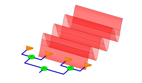
All antennas fed with equal phase offset.
The simplest way to do this is with a ‘corporate’ feed that consists solely of 2 way combiners. To add more antennas we simply add more splitters. With this design the distance that the signal travels through our combining network are always equal (provided that our combiners are have zero phase offset). Unless blank some terminals with terminators, we also can only create arrays with a power of 2 number of antennas (2,4,8,16 etc..).
Make it reliable, Make it reconfigurable
My design goals here are reliability and reconfigurability. I do not want to be trying to build phase matched cables that work at 6GHz, and I do not want to be creating multiple parts to build different sized arrays.
Reliability – Well, i’m not sure this is the right word. But as I said, I don’t want to mess around making phased matched cables. It’s no fun. As such I will be using fixed PCB microstrip traces to maintain the correct phasing of my signals between. This will have a big drawback in that I will need to choose a fixed antenna spacing(more on this later).
Reconfigurable – What I mean here is being able to assemble a relatively small number of parts together to create arrays with different numbers of antennas. In my design, I will be able to create 1×2, 1×4, 2×2, 2×4 and 4×4 arrays using multiple copies of the same part.
Spitter-spacer unit element
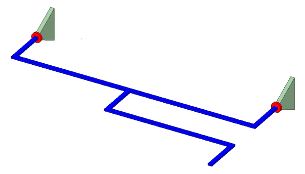
Splitter-Spacer Single Element
The above is the basic design for my splitter-spacer element. The dog-leg on the common port allows me to assemble multiple units together into a larger array. With 2 antennas together side by side, I should get a narrower beam pattern in azimuth.
Creating bigger arrays
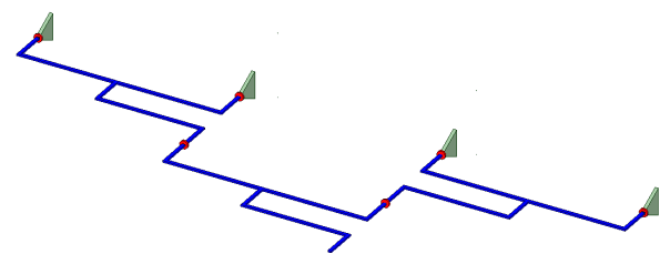
1 x 4 Regular Array
That looks easy. This should give me a really narrow beam in azimuth.
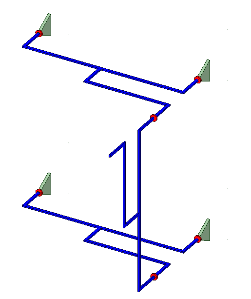
2 x 2 Regular Array
Still manageable, this should reduce the azimuth and elevation beamwidths.

2 x 4 Regular Array
Now were talking! This is one helluva an array. But we can go one step further.

4 x 4 regular array
“OMG – That’s just silly. This would take 15 splitter units to build this. It’s never gonna work! The loss in this feed network is going to be sky high.” Yes, I agree, I doubt I will ever build this beast.
“That’s all well and good, but…
…you said ultra-wideband. These aren’t even proper splitters.”
Okay, okay. This is true, the splitter-spacer as drawn here will not work(not at all!), but I wanted to show the concept before discussing the complexity of making one of these elements really work as an efficient and wideband splitter. I will get to that in good time (probably part 3). Before, I discuss that, I need to work out the antenna spacing which will be the subject of part2(coming soon!).


Leave a comment