Update – this antenna was professionally measured at AntennaTetLab – results here
Follow this link to see more info on the original creation of the Palm Tree Vivaldi Antenna developed by Dr. Alexandre at the Laboratory Maxwell in Brazil.
Final Antenna (The Palm Tree Vivaldi Antenna)

Final Antenna
Here is the final antenna. I am still waiting on some SMA connectors for the 1mm PCB. For now I have bodged a 1.6mm SMA connector onto one of the boards for testing.

Antenna with temporary 1.6mm SMA
The antenna measures about 90mm x150mm x 1mm so is extremely portable.
S11/Return Loss/SWR
Return loss or SWR(Standing Wave Ratio) is a measure of how much of the power that you send to an antenna is reflected back to the input port. This may also be called an S11 measurement. Return loss and SWR are basically 2 ways of representing the same thing and it is fairly easy to convert between measurements if required. SWR is given as a ratio while Return Loss is normally(but not universally) quoted in decibels.
Lower SWR and Return Loss numbers are better. An SWR of 1 represents a perfect match and equates to negative infinity return loss (when measured in dB).
Of course, just because power is not being reflected does not conclusively infer that the antenna is working (a 50ohm resistor has an excellent s11, but is not a good antenna). It is however in many cases a really good proxy measurement. In the case of this antenna, some of the reason for the excellent S11 performance(especially at higher frequencies) is due to the lossyness of the FR4 material.

Return Loss
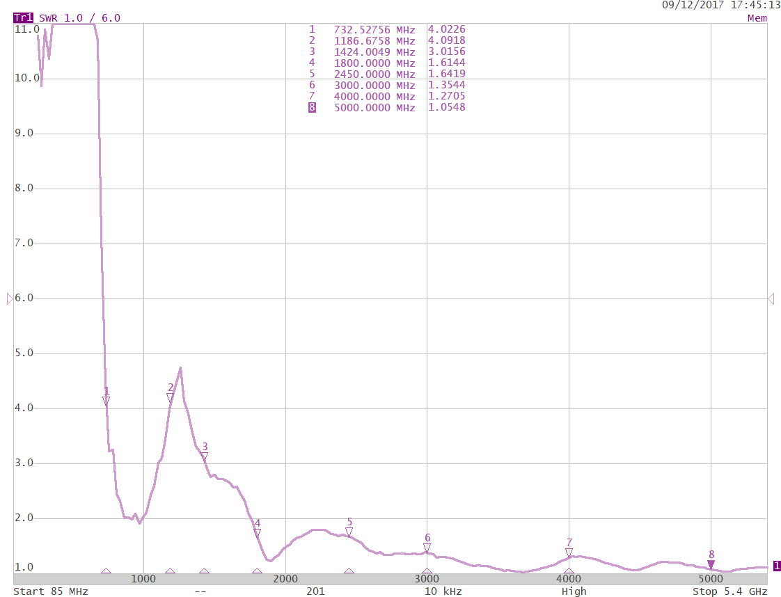
SWR
One feature that is prominent in these plots is that there seem to be two distinct regions of good performance. In the region above about 1.7GHz the antenna is working as a directional travelling wave antenna. When we look at the region around about 1GHz the antenna is no longer really working as a Vivaldi antenna. In this case is has become more like a dipole. This is also visible in the gain plots and radiation patterns.
Gain

Gain
As can be seen the antenna really starts to work well above 1.7GHz and the gain gradually increase from there. Currently I am limited to 6GHz for these measurements, but I do expect there to be good performance at least up to 10GHz and possibly beyond.
At the lower frequencies (~1GHz to 1.6GHz) the antenna is basically providing omni-directional performance. While it does not have any gain, I still consider that in many circumstances this performance is still useful. In fact as we drop down to about 600MHz and the gain becomes negative(primarily because of the poor S11 at this frequency), I would still consider the antenna to have enough performance for many purposes as the gain is still probably higher than a telescopic monopole antenna that has not been tuned to the correct length.
One interesting way to look at antenna gain is to convert it into an Effective Area(also called Effective Aperture). Effective Area is a measure of how large the antenna looks to the incoming EM wave. The chart below shows the previously measured gain figure converted into Effective Area.

Effective Area
As can be seen from this chart the antenna has an average Effective Area of about 45cm.sq. We can imagine this as the antenna having an area perpendicular to the incoming wave of about 9cm x 5 cm as shown in the image below.
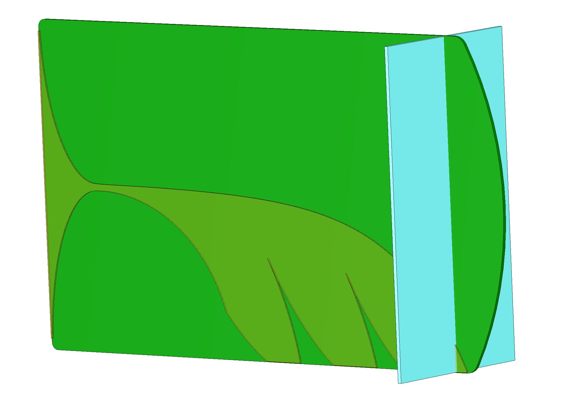
Effective Aperture(Average)
If the antenna had an Effective Area that did not vary with frequency we can do the reverse calculation to show what the expected gain would be. The chart below shows just this.

Gain plotted with expected gain for given effective area
When we do this reverse calculation (A_eff to Gain) we can see that my Vivaldi antenna follows fairly closely. This is fundamentally the reason why for an antenna of fixed physical size it will have less gain at lower frequencies. In reality this loss of gain is exactly matched by an reduction in free space path loss as the frequency drops. In fact it can be seen as a side effect to the way we have by convention decided to include frequency in our definition of path loss.
Radiation Pattern
I am currently struggling with creating Polar plots for all my measured data. The image below shows an example I have been able to create. The peak of this plot is 5.8dBi and the centre is -15dBi. I will try and update with more plots when I find a more streamlined way of creating them.

2400MHz Azimuth
SDR signals
I will try and include some comparison spectrum plots between this antenna and a standard mag mount.
Applications
Clearly such a wide band antenna can be used for multiple applications. The list below is not comprehensive by any means.
- WiFi – both 2.4 and 5GHz
- Bluetooth
- Cellular 1800/1900/2100/2600 reduced performance for 800/850/900
- ISM 868 or 915 (reduced performance)
- FPV vidio and Telemtry
- S-Band
- C-Band
Enhancements(what next?)
I have a few ideas of where to go next with this project. Please let me know in the comments if you think any of this would be useful.
3D Printed Brackets, Spacers and Stands – Likely to be the first enhancement as I need these myself. I will place the STL files on Thingyverse for anyone to download or modify.
Array feed network – This would be a number of UWB splitter/combiners with the correct spacing(or possibly a couple of spacing variants) for linking multiple antennas into an array. One cool trick that you can do with this is to rotate alternate antennas to create a 180° phase shift. When combined in an array these create a very tight null that can be used for direction finding. The intention of this is to provide a set of building blocks so that people can experiment with building there own array configurations.
On-board LNA – This would be a receive only version of the antenna with a wide band low noise amplifier mounted directly on the antenna PCB. There are a few of options for powering this such as an on-board coin cell or AAA batteries(dependent upon power consumption) alternately it should be possible to use DC bias output available on many SDRs to provide power.
Own One
I have a small batch of 15 antenna PCBs (ordered 10 and the Chinese PCB fab over delivered). Some of these are reserved for my own use and to give to a few friends. The remaining batch (probably about 8) I intend to stick on either Ebay or Tindie. If they prove popular I may run some additional batches. My intention is to keep the cost low. Probably about £12 each or slightly more for a pair. Does this seem reasonable? Let me know in the comments. My intention is to cover my costs and hopefully have a little left over to fund the development of some enhancements as described above.
As stated earlier, I am still awaiting delivery of the SMA connectors so any sales will likely to be in the new year.
[update July 2019] – Shortly after releasing this antenna, my blog was picked up by RTLsdr and sales went crazy. I have since sold over 300 and continue to use my own for lots of interesting projects. I was able to spend many many weeks on the development of the new Spiral antennas, where I learned a ton of stuff and hopefully was able to communicate some of that knowledge back to the community. Many thanks to all. 🙂
These antennas are now available via my Tindie store.


I received the two antennas yesterday, put them on the analyser and spot on !! Just need to find a way of combining the two and to experiment with them as a dish feed. Great work , keep it up 🙂
[…] my Palmtree Vivaldi antenna, I did a similar calculation. As a planar antenna, its hard to easily see what the aperture is, but […]