Why Spacing Matters
Firstly, the antenna array I am designing is a fixed in-phase array. Hence we assume that the total path length from each antenna to the single input/output connection are the same length. This makes the design and analysis much simpler, especially for an ultra-wide-band design.
In my design signals that arrive at right angle to the antenna will add up co-herently (in-phase)
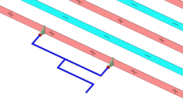
Signals arriving from boresight add up in phase
In the next image, the signal is arriving from a different angle. However the signals are sill adding up coherently(in-phase). This will create gain in this undesired direction. This is called a grating lobe.
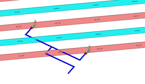
Spacing greater than wavelength allows array gain at undesired angles
Grating lobes can only exist when the element spacing is greater than half the wavelength(distance between positive and negative wave peaks).
So what is the ‘best’ spacing?
With that knowledge, it is trivial to run the basic math to work out the maximum spacing at each frequency as shown in the table below..
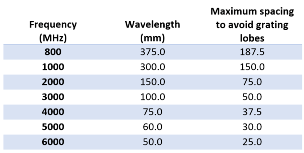
Oh dear….
To satisfy this at 6GHz, my maximum spacing is 25mm. That’s fairly close together and leads to two problems.
The first problem is purely practical. My antenna elements are 90mm tall. For any spacing less than this I will not be able to stack them vertically.
The second problem is best illustrated with some examples. Below are two plots generated by this excellent on-line array factor calculator.
-
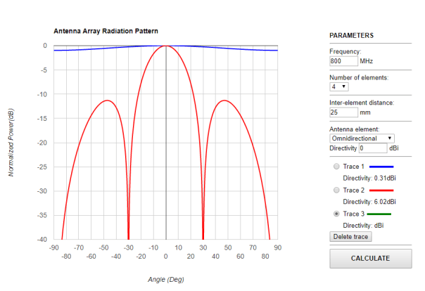
- 25mm (blue=800MHz,Red=6GHz)
-
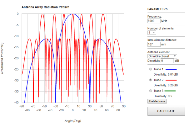
- 187mm (blue=800MHz,Red=6GHz)
As can be seen if we set the spacing to 25mm to suit an 6GHz array, we have virtually no benefit from having an array at 800MHz. If we set the spacing to 187mm to suit an 800Mhz array we create lots of grating lobes.
Is there an answer somewhere in between? The short answer is no. The long answer is a bit more complex. Perhaps when we combine the array with our already directional antenna these grating lobes will matter less. But first lets talk a little about array factor.
Array Factor
Fairly simply, and avoiding the math(google will find this for you if needed), Array Factor tells you the effect that the array geometry(and weights/phase offests) adds to the antenna directivity. In my case the weights are all 1/n, where n is the number of elements and the phase is zero. The two example array factors shown above do not tell us what the resultant beam pattern will be for the antenna.
In fact, and rather obviously the real-world antenna gain will be a function of the array factor and the directivity of the component antenna elements. Ignoring, the fact that the antennas are closely located and will have all sorts of (hard to calculate) mutual coupling effects, we can in fact just multiply the array factor pattern by the directivity of a single element to give us a good idea of the likely resultant array directivity.
As the Array Factor changes with frequency and the antenna element directivity changes with frequency, this is somewhat non-trivial. I do however have a full set of directivity plots from Antenna Test Lab and the rest is just math. So its really just a case of creating a large spreadsheet.
The birth of a Mega-spreadsheet
So here it is, the behemoth spreadsheet. You can download a copy to play with yourself here. This spreadsheet works out the array factor for linear arrays up to 9 elements long and allows me to tweak various design parameters. Additionally, I can take the Array Factor and combine it with my real world measured element patterns.

Array Factor for 10cm spacing(700MHz to 6GHz)
ArrayFactor Tab
- Set the frequency sweep step by changing the first row data.
- Select how many elements we would like to use(by setting 0 or 1 in the green highlighted boxes)
- Set the base element spacing. This gives us a single value to scale the array.
- Set the relative element spacing for each element.
- The 3D plot show how the Array Factor changes across frequency
AntPattern Tab
- Here you can put your measured antenna element pattern for each frequency.
- Alternately you can use the Basic Pattern tab to mathematically generate a antenna pattern. (I haven’t put too much effort into simulating patterns for real antenna types, but feel free to play)
- The table currently contains a cubic interpolation of the results from Antenna Test Lab.
Combined Gain Tab
This is just the product of the Array Factor and the AntPattern.
Combined Directivity Tab
This is a normalised version of the Combined Gain. Results are presented as a 3D chart as well as cartesian plots for various spot frequencies.
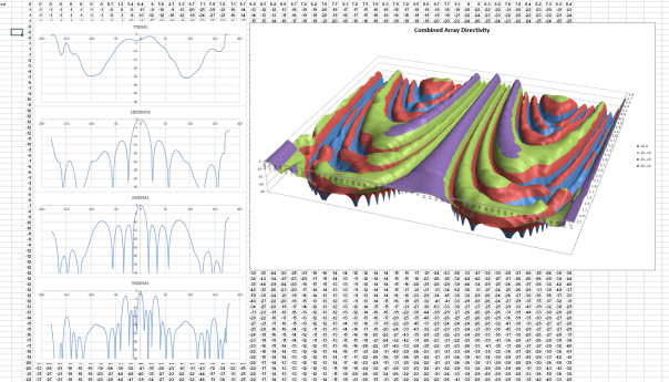
Array Factor Combined with Antenna Element Pattern with 10cm spacing (700MHz to 6GHz)
The results above show a 4 element linear array with 10cm uniform spacings. Areas of the 3D plot that are green,red or blue have gains at least 10dB down on the boresight gain, in this case true for frequencies up to 2.7GHz
Predicted Gain Tab
An attempt to work out what the real world gain would be. I’m not sure this is possible unless I consider the full 3D pattern. Please do not trust these values.
The Answer
The calculatons show that I should be able to build an UWB array with sidelobes below about 10dB with an element spacing of about 6cm. At the bottom end of the frequency range I don’t get much benefit from using an array though. With the spacing at 10cm the low frequency boost is actually worthwhile.
So should I sacrifice the ability to stack the elements vertically(remember PCBs are 9cm tall)?
Should I build two variants? An upper band and a lower band version.
Perhaps, its possible to create a single splitter that allows the user to choose 60mm or 100mm spacing, or a combination of both. I think there is a way….
In the next posts I will talk about splitters and impedance transformers.


Leave a comment