Why?
My original Palm Tree Vivaldi Antenna has proved amazingly popular. Much more so than I originally intended. The design aim for this was primarily for it to be small and portable.
When deciding what to do next I decided to create a survey and see what other people were interested in.
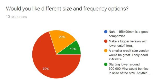
R&D Survey Results
The overwhelming response was that people wanted a bigger version that would cover lower frequencies. I can understand this, there are loads of interesting signals below 800MHz.
The next logical frequency of interest was the 400MHz band as it covers the 433 ISM and 446 PMR radio. Now I could have simply scaled up the Vivaldi design, but to give a good gain pattern this would end up about 380x650mm in size(for directional gain the mouth of the antenna needs to by 1/2 wavelength). That’s enormous, unwieldy and really difficult to ship. PCB manufacture of such an antenna would not be practical and a much better solution would be to use solid aluminium. If you want this type of antenna then I can highly recommend Pieter Belings RFSpace Vivaldi Antennas.
Hence, I have decided to build a Spiral Antenna
Spiral Antenna
- Equianglular Spiral Antenna
The key property of the spiral antenna is that its lower cut off frequency is defined by the circumference of the antenna rather than the height(depending on orientation).
At 400MHz, Wavelength is;
λ = 749mm
A Vivaldi antenna opening would be;
λ/2 = 374mm
A Spiral antenna diameter would be;
λ/π = 238mm
Nearly 40% smaller. And as the Vivaldi is generally longer than it is high so it’s even more of a saving in this dimension.
The upper wavelength of the spiral antenna is defined by the initial starting diameter. In my design this is 10mm, and hence the theoretical upper frequency is about 9GHz. I doubt this antenna will work to quite that frequency because of losses in the feed structure.
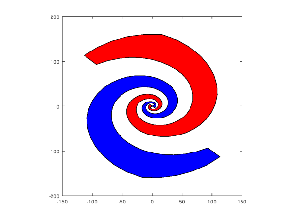
Circular Polarisation
Spiral antennas have circular polarisation. There is a ton of information about this on the web so I wont go into detail here, but what it means is that the axis of the electric and magnetic fields rotate as the signal propagates through space. It can either rotate clockwise or anti-clockwise.
In antenna theory we use the term Right Hand and Left Hand polarisation as this description encompass the propagation direction as you will see. Take your right hand and hold it up to the image above, your fingers should curl in the direction of the spiral. Stick up your thumb and it will point in the direction of the Right-Hand Circular Polarisation(RHCP). Now imagine flipping the antenna over so that the direction of the spiral flips also. You will now need to use your left hand so your curled fingers follow the spiral. Then antenna should radiate Left-Hand Circular Polarisation(LHCP) in the direction of your pointing thumb. Hence the spiral antenna pictures has RHCP upwards and LHCP downwards.
A quick note on Reflections
When Linearly polarised signals are reflected off perpendicular surfaces the polarisation is unchanged. This can be exploited in antennas to create a reflector that reflects antenna backlobes and reinforces the forward gain.
When circularly polarised signals reflect the handedness of the polarisation is also flipped. Technically this occurs because the E-field is reversed when it hits a conducting surface and as explained by Poyntings Vector Rule is the reason the propagation direction actually reverses at all. This video explains it better than I ever could.
The upshot is that a LHCP back lobe can be reflected by a 1/4 wave spaced reflector and add to the gain of the RHCP forward lobe. Just like with regular linear polarisation. Whohoo!!
The next important property of CP is that it is not necessary to align the antenna with the orientation of the incoming signal. For linearly polarised signal we will receive a 3dB polarisation loss, but never be hit with the total signal loss that we would expect with orthogonal linear polarised antennas.
So far I have discussed ‘perpendicular’ reflection only. Most structures a propagating signal will encounter are not perpendicular to the travelling wave. When this occurs(as it always does) the polarisation of the reflected signal is changed. The received signal at any point will have a complex mix of all these different reflection polarisation.
Fading and Multi-path
Another little known fact about Circular Polarised antennas is that they are generally less susceptible to deep nulls and fades caused by unwanted reflections. You may have experienced fading with your car FM radio. Occasionally you pull up to a stop and the signal just disappears. All you need to do is creep forward by a foot or so and its back. This is caused by reflections adding up in anti-phase to create a sharp null.
Why CP helps with multi-path is complex in real world scenarios, but many empirical studies back show it to be true. One reason for this is that single reflections(and all odd numbers of reflections) are have flipped polarisation (LHCP to RHCP or visa-versa) the receiving antenna does not hear them and they can not add up destructively.
Curiously, it has been shown that many of these benefits still exist when receiving linear polarised.
The long and short of this is that if you are willing to take a 3dB hit on the best case received signal strength, you can benefit greatly from a much more robust link. And if the incoming signal is actually circularly polarised then more the better.
A choice of spirals
There are two main types of spiral antennas and some hybrids and offshoot designs to choose from. These include non-planar spirals on cones and spheres and weird sinuous patterns. The two most common however are the simple Archimedean Spiral and the Equiangular Spiral as shown above.
Archimedean Spiral

Archimedian Spiral
In this design the rate of increase of the spiral diameter is constant. Generally, as with many designs, it is generally made with the wire thickness equal to the sire spacing.
It has advantages in being simple to construct(can be made and fed with coiled coax). It also has good circular polarisation all the way down to its lower cut off frequency( the outer ring of the spiral).
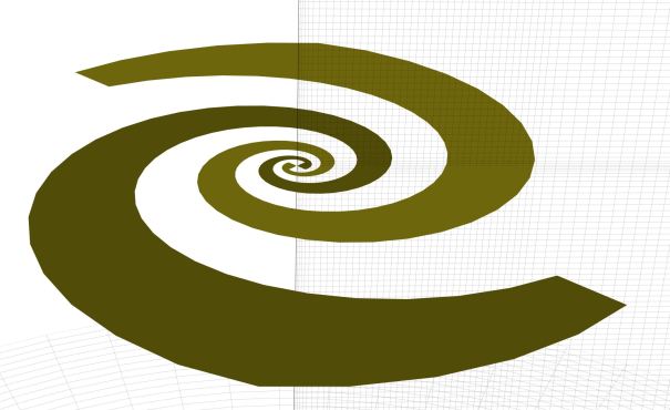
Equiangular Spiral
Equiangle Spiral (Log Spiral)
With this design the rate of expansion of the spiral is logarithmic and the antenna looks the same at any zoom level. It is often thought of as a true frequency independent antenna as it’s geometry can be entirely be described by angles rather than specified lengths.
For my purpose a key advantage of this antenna is that the physical length of the arms is shorter and thicker. This means that currents flowing through them will experience less ohmic losses. It also has a big advantage when the spiral arms are used to contain the antenna feed.
The Feed
Spiral antennas generally fed in a similar manor to a dipole with the each arm being driven in anti-phase from the centre. They have a high input impedance of between 100Ω to 200Ω. As such we can not directly feed them via a 50Ω cable without expecting some serious impact on the VSWR.
Many cavity backed designs use a direct connection to this centre point with impedance matching achieved by a tapered microstrip line. The limitation here is the depth available to achieve this transition without causing reflections.

Equiangular Spiral Antenna with tapered microstrip feed.
In my design I have chosen to feed the antenna via a microstrip line fed in the centre of one of the antenna arms. I have enough length in this arm to gradually thin the microstrip such that the characteristic impedance gradually changes from 50Ω to 120Ω. The later impedance being direived both from simulation(see my next post) as well as practical limitations of higher impedance tracks being too small to manufacture (or resorting to really thin and fragile substrates or 4 layer boards).
It can now be seen from the above image why the Equiangular (logarithmic) Spiral was best for my application. Imagine how long this feed would be with an Archimedean spiral. The losses with a cheap FR4 substrate would be horrendous.
Next step
We’ll that’s the plan. In my next blog post I will show some of the details about how this antenna was simulated using OpenEMS.


Very nice post!
[…] post is split into three parts. The first post introduces us to his motivation and talks about what spiral antennas are. The second post discusses the modelling and simulation of […]
[…] post is split into three parts. The first post introduces us to his motivation and talks about what spiral antennas are. The second post discusses the modelling and simulation of […]