
I am conducting a quick survey to help discover what developments people would most like to take my UWB antenna forward. I would be really grateful if you could take a few minutes to have your say.
I am conducting a quick survey to help discover what developments people would most like to take my UWB antenna forward. I would be really grateful if you could take a few minutes to have your say.

My next project after successfully building my Ultra-Wideband Vivaldi antenna is to use it to create a UWB antenna array. I will assume that most readers are at least slightly familiar with the concept of an array, I will give a quick introduction, but for those that want some background reading here is a good site to look at.
In essence we create when we sum the output of multiple antennas to increase the gain and directivity. Of key importance when we do this is to control the phase of the incoming signal that we are adding. I will be building one of the simplest forms of array, where all antennas are summed with an equal phase offset. This will have the effect of increasing the gain on the antenna boresight (and reducing the gain at other angles (I will get to grating lobes in another post)).
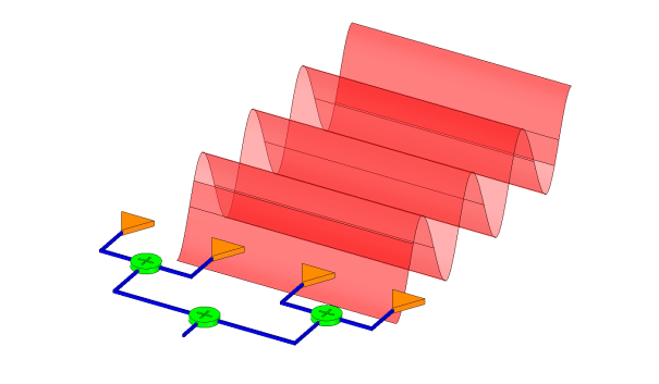
All antennas fed with equal phase offset.
The simplest way to do this is with a ‘corporate’ feed that consists solely of 2 way Read more ›

Update – this antenna was professionally measured at AntennaTetLab – results here
Follow this link to see more info on the original creation of the Palm Tree Vivaldi Antenna developed by Dr. Alexandre at the Laboratory Maxwell in Brazil.

Final Antenna
Here is the final antenna. I am still waiting on some SMA connectors for the 1mm PCB. For now I have bodged a 1.6mm SMA connector onto one of the boards for testing.

Antenna with temporary 1.6mm SMA
The antenna measures about 90mm x150mm x 1mm so is extremely portable.
S11/Return Loss/SWR
Return loss or SWR(Standing Wave Ratio) is a measure of how much of the power that you send to an antenna is reflected back to the input port. This may also be called an S11 measurement. Return loss and SWR are basically 2 ways of representing the same thing and it is fairly easy to convert between measurements if required. SWR is given as a ratio while Return Loss is normally(but not universally) quoted in decibels.

My chosen antenna design is a version of the Vivaldi antenna. The Vivaldi was named by fellow Brit Peter Gibson. It is believed that the name came out of Gibson’s love of classical music, and in may ways the Vivaldi antenna resembles the horn of a brass instrument.

Basic Vivaldi Antenna
Why choose this antenna? Well primarily it can be manufactures cheaply with conventional printed circuit technology. This allows me to have it built to a high level of quality and repeatability. Secondly the antenna is capable of incredible bandwidths and also has a reasonable level of gain. In fact, I don’t think there is another antenna in this form factor that can provide more gain over a similar bandwidth.

Having backed the new LimeSDR mini crowdsupply campaign, I am expecting delivery of a highly capable software radio with the ability to receive and transmit at frequencies up to 3.8GHz. This is brilliant and the small size means that it can always be in my bag as and when I need to investigate some RF signals. But what antenna do I use?
Most people would settle for a mag-mount monopole, but these are inherently narrow band and while you can telescopically adjust the length it is pain and hard to get the frequency spot on. Also as an omni-directional antenna its not much good for hunting unknown signals.
What I wanted was a small very wide-band antenna with plenty of gain. The solution is the Ultra Wide Band(UWB) antenna. In this series of posts I will discuss some of the candidate antennas, detail why I selected the one I did, discuss the chosen design, introduce some of the tweaks to improve performance, and provide some measured results.
PEI is the new wonder bed material for 3D printer. It has many advantages. Plastic sticks when hot and releases releases easily when cold. No need to apply messy sprays, glues and concoctions between prints. It leaves a nice smooth bottom layer, just like glass. It’s great!!
Hence I was keen to add this to my Wanhao i3’s list of mods. PEI is difficult to get in the UK at a reasonable price, but I was able to get some imported from Amazon US for about half the price as Mr Ebay UK wants to charge me. I also got some 3M 8153LE double sided adhesive as recommended by the great DC42.
The question then was how to attach it to my print bed. My PEI sheet is 1mm thick, but this will still bend under ABS warping forces so it really needed to be bonded to something more rigid. I could have used glass, but then I wouldn’t be able to flex the bed at all in case of a really well stuck part.Instead I decided to use some 1.6mm 2 sided copper clad FR4 (PCB material). The copper layers should work really well as a heat spreader and having it double sided would probably help stop any temperature induced warping.
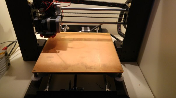
This gave me a rather cool option. I could cut this into whatever shape and size I wanted, and it had always annoyed me that when printing anything close to the 200mm bed size of the Wanhao I would risk the nozzle falling off the edge. The Wanhao Mk2 heated bed is actually a bit larger than the 200mm so why not cut the FR4 to that size.

The mounting screws on my V2 Wanhao i3 are not countersunk and sit proud of the bed, which presents a problem and opportunity. With the FR4 it is no drama to drill some holes 5mm from the edge for the screw heads to sit inside. But hey, why not use those screw heads to hold the FR4 in position too. Good idea eh!

I drilled the holes with a 4/4.5/5mm drill bit (can’t remember which). This made the holes ever so slightly smaller than the head of the screw. At this point the FR4 could be offered up to the bed to check alignment. All was good so I used a coutersink bit to enlarge the base of the hole slightly so it fit snugly on top of the screw heads. Time will tell if this is going to hold it in place securely enough. My build plate is still slightly tacky from the removal of the p-Buildtak (see bottom), but I can always attach the trusty bulldog clips if required.
I then cut the PEI sheet to size and bonded it to the surface of the FR4 with the 3m adhesive sheet and Bob’s your mothers brother the jobs done.
Two prints in and it’s really working great. I will probably need to lightly sand the PEI at some point, but for now it’s working fine as shipped.
Aside – The Wanhao i3 comes with a factory fitted sheet of pseudo build tak place directly on the bed. This can be peeled up, but leaves a horrid mess of glue on the surface. Scrapping this off is an absolute ball ache. I found the best way was to use a liberal dowsing of acetone and lots of kithen roll. This worked a like a charm.
UPDATE – 3 prints in. All relativly big. No failures. No warping and amazingly smooth bottom layer. https://youtu.be/sOeceZ6h1Qg
Hi, I’m just setting up this test blog to see what wordpress can do. I may use this site or derivative to post things about electronics or other stuff eventually. For now I’m just playing with the tools.
| Brenda on There is no Loss in Free Space… | |
| hexandflex on There is no Loss in Free Space… | |
| Gene on There is no Loss in Free Space… | |
| tittiger on Getting Started with the NanoV… | |
| Alex Cooks on Ultra-Wideband Antenna Lab… |

