Now tested by AntennaTestLab. For now see results here
Electromagnetic simulation software can be very expensive. While some software is cheaper, it often comes with either technical or artificial limitations. There are however a couple of free alternatives.
NEC2 – Originally written by Lawrence Livermore National Labs, NEC2 was open sourced many years ago. Since then a couple of users have created good free or low cost front ends for it. 4NEC2 is my personal favourite. The best feature is it’s speed, especially if you can find a copy of NEC2/MP that makes good use of multiple core moderns processors. The big limitation is with dielectrics. Everything in NEC2 is either wire, free-space or earth.
OpenEMS – A Finite Difference Time Domain (FDTD) tool that uses MATLAB or the excellent free Octave as a front end. It was created by Thortsten Liebig at the General and Theoretical Engineering University in Germany. As suggested in FDTD, OpenEMS uses a time-domain approximation of Maxwells equations to calculate the results. The big advantage of OpenEMS over NEC2 is that it can handle bulk dielectric materials with different EM properties, I will need this to simulate an antenna on FR4 with an Er~=4. While it may not seem it at first, being able to generate geometry mathematically in is another advantage. This is especially true for a spiral antenna. Hence this is the package I decided to learn and use for this project.
Dont Panic!!!
So, lets get this out of the way first. OpenEMS looks pretty intimidating to a new user. It’s really not that bad though. Honestly.
Installation is easy. This is not a tutorial, so do go to OpenEMS and follow the excellent guides there.
On Windows], Octave has a really good installer wizard, just run it, it works fine. Don’t worry about not having MATLAB, for the purpose of using OpenEMS Octave works just fine. OpenEMS is a simple downloaded zip file that you extract to your c: drive(or anywhere else if you want to be different). You only need to add one line to the Octave startup script and type setup at the Octave command line to compile the scripts and you are ready. Paraview is optional. The majority of the plots you will need are generated directly from Octave and may not need to install it at all.
Once installed there are a series of examples and tutorial files included in the OpenEMS/MATLAB/tutorials folder. They are an excellent start and the tutorials on the OpenEMS website will guide you through them really well.
I would guess that the biggest hurdle for many is using Octave/MATLAB. If you haven’t done this before then it is probably worth doing a few tutorials on this. For 99% of tasks Octave works exactly the same as MATLAB and most code will run in either. You will need to understand how Octave generates, manipulates and references vectors.
Give it a try.
My Model and Simulation Results
I have chosen not to attempt to simulate the feed strucutre. The 120ohm tracks(impedance chosen from these simulations) are very fine and would require and exceedingly fine mesh to simulate. Instead I only simulate the arms of the antenna with a lumped feed at the centre that magically creates a input port without and cables or tracks.
Meshing Meshing Meshing!!!
The success of your simulation is really dependent on how your model is meshed. And unlike many of the commercial solvers, it’s up to you to generate it.
The mesh is how OpenEMS breaks down you model into individual unit cells.
Here is mine:-

OpenEMS Mesh
As can be seen I have used a cylindrical mesh. This really seems to make sense for this antenna type. The mesh is naturally finer in the centre where the tracks are thinner and I expect the higher frequencies to be radiated.[edit-i have also tried this with cartesian mesh and it works fine too]
Unlike the simper tutorial antennas this design takes some time to run. Up to an hour on a quad core i7. Really this is down to the required mesh density required for the high frequencies and fine structure of the centre of the antenna and the need to have a large bounding box that needs to be at least 1/2 wavelength from the structure.
Much time later..S11
So here are the simulation results.

Feed Point Impedance
That is a very stable plot of input impedence. The imaginary component stays very close to zero over my 400MHz to 2GHz range and the real impedence is well matched to 120ohms.
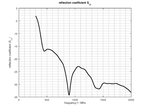
Return Loss
With OpenEMS set to use a 120ohms source impedance as derived from the previous plot, I can expect an return loss to look something like this. Anything less than -10dB is really good. These results are amazing!. If I can achieve anything near this in the real world I will be very pleased.
Radiation Pattern and Gain
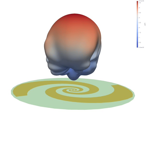
RHCP Directivity 900MHz
This plot shows the Right-Handed polarisation. The peak gain is heading directly upward with very little back lobe. The LHCP plot is just the mirror image of this with peak gain straight downward. The simulation predicts about 4.7dB of directivity.
Conclusions
OpenEMS is a powerful tool for simulating antenna and other RF circuits. I was able to design and simulate an Equianglular Spiral Antenna that predicts good results. I will shortly be receiving manufactured PCBs that I will conduct initial tests on and see how closely simulation and measurement match.


[…] original simulations predicted near perfect VSWR and a quick look at the plot below reveals just how well this turned […]
Can spiral inductors be designed and simulated in openEMS?
Yes, I am fairly sure you can do that.
Hi. I’m trying to simulate an antenna and I am facing problems to get the radiation pattern.
I have the design on Kicad and also in a MATLAB description because I draw it directly to get a chance to make it work.
Could you share you script used for simulate? Could I send to you my design to see if is something really wrong?
Thanks you in advance and congratulation for the nice job done in this project!
If you want to send your script to hexandflexhelp@gmail.com I will try and take a look. No guarantees though as I haven’t messed with OpenEMS for some time. You could also ask on the OpenEMS forum.
I have sent you the results of my simulation. I think the issue was with the distance of the boundary to the antenna structure. I increase this to lamdda/4 and switched to PML_8 and am getting better results (reflection coefficient <1).
You might also want to try the debug-PEC function to check that the antenna is adequately meshed. http://openems.de/index.php/Model_Visualization.html
Wow this is incredible. Thanks for writing this up. Would you be able to share the Octave simulation script you used to simulate the antenna?
Thanks again!