
Antenna in Test Lab
The original aim for this antenna was to be a general purpose antenna that worked down to 400MHz. The results are now in and I am really pleased with them. The antenna was tested by AntennaTestLab in a full anechoic chamber with a 3D positioning system to automatically rotate the antenna. ATL use a dual polarized (horizonal and vertical) Vivaldi antenna to measure the radiation pattern. By recording both the amplitude and phase of each antenna they can use clever math to calculate the circular polarized gain. Clever stuff eh?! Take a look at ATL’s writeup here
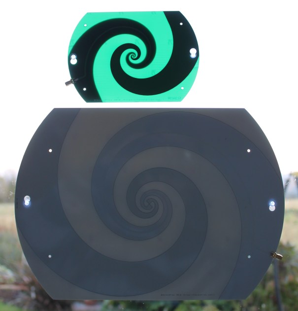
>300MHz and >800MHz(green) Antenna Mounted on Window.
The larger antenna (SPI300) measures 321mm x 227mm (12.6″ x 8.9″). The smaller antenna (SPI800) measures 160mm x 113mm (6.3″ x 4.5″).
I have also created a smaller >800MHz version (green antenna above) that is cheaper to build and ship, but will be better suited to higher frequency operation. There will be a lot of read-across from the results here, but this post is specifically about the larger original version that has been more thoroughly tested. Side note, the green colour was just chosen as the default PCB option for a prototype. I think it looks great though, especially when back-lit. I may need to offer such a colour choice at some point via my Tindie store.
Some may have noticed the odd shaped mounting holes in the PCB. These can be used to attach the provided suction cups enabling the antenna to be easily mounted on a window. It hopefully answers one of the questions I see regularly on various forums from users who live in apartments and are not allowed to add anything to the external structure of the building. You can stick this antenna onto the window and get a pretty good performance across a wide band. Perhaps you are staying in a hotel and want to play radio?.. Again this is ideal.
VSWR/Return Loss/Efficiency
My original simulations predicted near perfect VSWR and a quick look at the plot below reveals just how well this turned out.
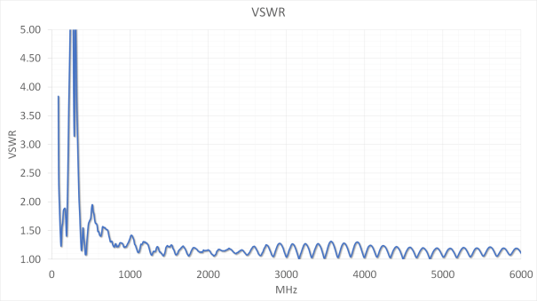
VSWR is much below 2:1 from 400MHz up. In the case of a transmitter this means that power delivered to the antenna is not reflected back to the radio. While this isn’t the whole story (see below) it is still an excellent start. Another interesting and accidental feature is a second region of good VSWR from 90MHz to 200MHz. While I haven’t got efficiency or radiation patterns for this region it tallies well with my testing where I was getting very clear reception in the FM radio bands. The antenna is not really working as a spiral antenna in this region and as such, the polarization will probably be highly elliptical. But if it works it works, hey!
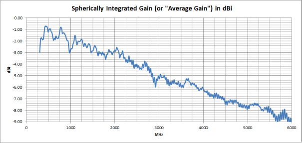
“Low VSWR does not always equate to good radiation!” is a line that is have rolled out many times over the years and this antenna is a good case in point. One of the downsides to my design is the need for a very long feedline that spirals through one of the spiral arms. On cheap FR4 this causes a lot of loss at higher frequencies.
The plots below generated by AntennaTestLab are created by integrating all the radiated power from every direction (measurements are actually in discrete steps). This gives a very good proxy for antenna efficiency. Basically, if the power isn’t radiated or reflected back to the source it’s probably being dissipated as heat.
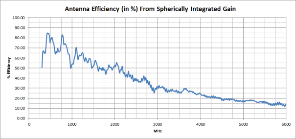
Is this a problem? Well, that depends upon the application. Clearly, it reduces the ultimate gain that the antenna can achieve. If you are transmitting higher powers (and higher frequencies) you may eventually start to see the temperature rise, but over such a big area with the large amount of copper, it will need a lot of power to cause damage.
As can be seen, this antenna would really benefit from a better low loss RF substrate. I may one day look at producing a pro version, however, I fear this would make it unaffordable for too many people. Please leave a comment below if you feel this would be useful.
Gain and Radiation Pattern

RHCP/LHCP Antenna Pattern Swept from 300MHz to 6GHz
The above animation shows both Left and Right Hand circular polarization realized gain over a sweep of frequencies. High Quality Verison. If the antenna was pictured on this plot you would see the only see the 1mm thickness of the PCB as the gain is broadside. Manufactured antennas are marked LHCP/RHCP on each side of the PCB so you can tell which way is which.
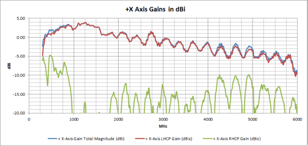
Realized Gain Plots
Conclusions
“All antennas “work”. Some just work better than others!!”
As with all great scientific discussion, when someone asks if an antenna “works?”, the unsatisfying answer normally received is, “It depends!!!”. Maybe this is why people don’t like “experts”. It is however true, and really depends upon exactly what you need it to do. There is nothing wrong with using a paper clip if it fulfils your requirements. I will regularly use antennas outside of their design bandwidth. If the distance is short and or the signal is strong, it may not matter. When the challenges mount, the signals are weak and the propagation environment becomes challenging, you may need to think more carefully.
So, does this antenna work? ….It depends!! You really will need to decide for yourself. I reckon that it’s pretty good for a wide variety of applications. I am happy to try and answer specific questions, either in the comments section or via email (hexandflexhelp@gmail.com).
These antenna will be on sale via my Tindie store starting around late November 2018.


If want optimal performance the ratio between the conductor width and the dielectric gap width should be equal. It will then be self-complementary. Still, very cool series of write-ups and decent result.
I’ve always felt that openems was unapproachably complex but you make a good argument for it. I’ll have to give it another go.
That seems to be the case. This design is self-complementary.
I have used HFSS in the past and its pretty complex also. As I mentioned the biggest obstacle is having a basic grasp of matlab/octave usage first. To learn both OpenEMS and matlab at the same time would be a challenge.
[…] Spiral Antenna – Part 3 – Results and Suckers […]
Have you considered using a teflon sheet as your dielectric? It’s cheap enough. I don’t know how you stick anything to it though?
I use Matlab a good deal but struggled with openems. Using polar coordinates, I couldn’t get a conductive loop to close. They always had a break at theta = 0. I finally gave up.
I have used teflon and copper tape before. It works, but isn’t very robust or easy to build in a repeatable fashion. Maybe you have a rounding error.